This page includes affiliate links. If you click and purchase, I may receive a small commission at no extra cost to you to support this blog.
This is part two of my review of the xTool D1 Pro 2-in-1 laser kit. In part 1 of the review, I wrote about the assembly, and software of the D1 Pro and tested the 20W laser module with different materials. This part will cover the installation of the infrared laser module and tests of its engraving capabilities.
The 20W blue laser module outputs a beam with a wavelength of 455 nm, the 2W infrared module outputs light at 1064 nm (which is the same wavelength that is used in fiber lasers). The wavelength makes a significant difference because different materials absorb light at different wavelengths. This means the infrared laser is able to engrave materials that the blue laser cannot engrave and vice versa.
The 1064 nm infrared laser module can engrave the following materials: metals (including gold, silver, platinum, aluminum, copper, zinc, titanium, iron, stainless steel, metal oxides, and alloy metals), leather, opaque plastics, some acrylics, stones, and circuit boards.
Due to its relatively low power of only 2W it is not really intended for cutting even though it is possible to cut thin metal foils (e.g. 0.02 mm copper).
The infrared laser spot size is approximately 0.05 x 0.05 mm which is smaller than the 20W which has a spot size of 0.08 x 0.10 mm. This means that the infrared beam will have a higher power density and can engrave finer detail.
First Look at the xTool Infrared Module
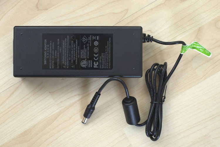
The infrared module was shipped in a separate box. The box contains the laser module, a 150W power supply and an installation booklet.
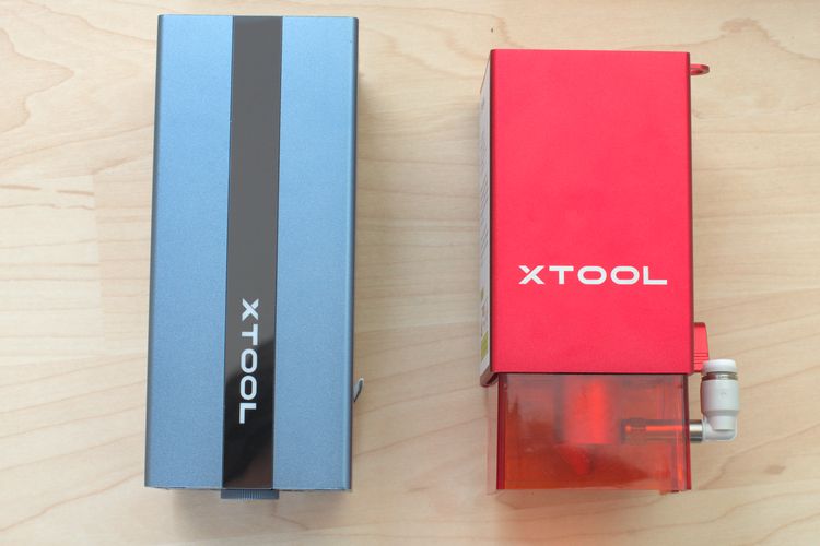
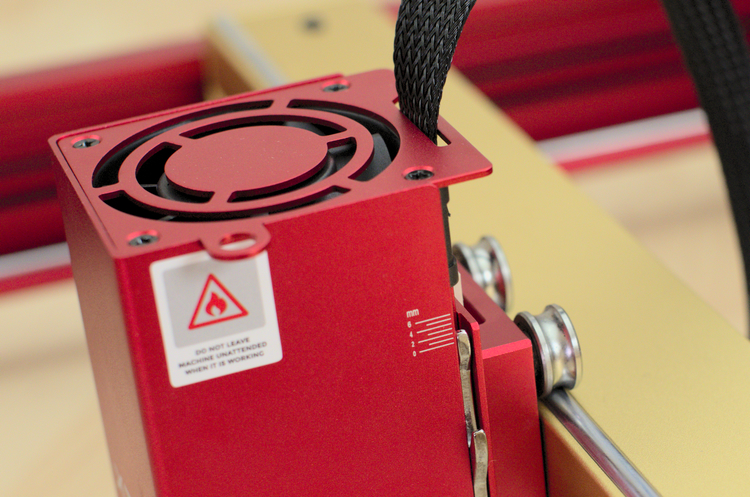
I have the gray version of the infrared module but it is also available in red. The infrared module is bigger than the 20W module even though it does not have the orange light shield around the bottom. It also does not have the option to install an air assist. As it is intended mainly for engraving metals and metals don’t produce a lot of smoke when engraved, an air assist is probably not necessary.
I would have liked it better if there would have been some shielding on the infrared module too. It only has one-tenth of the power of the 20W module but is still a class 4 laser which can cause permanent eye damage. Also infrared light is not visible and when working with materials such as metal, there is a high chance of reflections. So only use the laser with appropriate safety goggles!
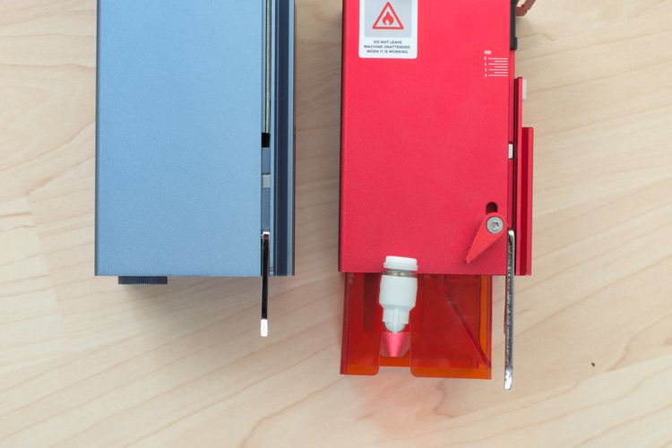
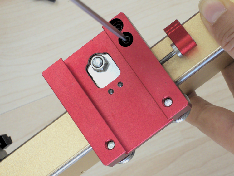
The xTool infrared module has the same swiveling focus lever as the 20W module only that it is just half as long. This is because it has a different focal length (more on that later).
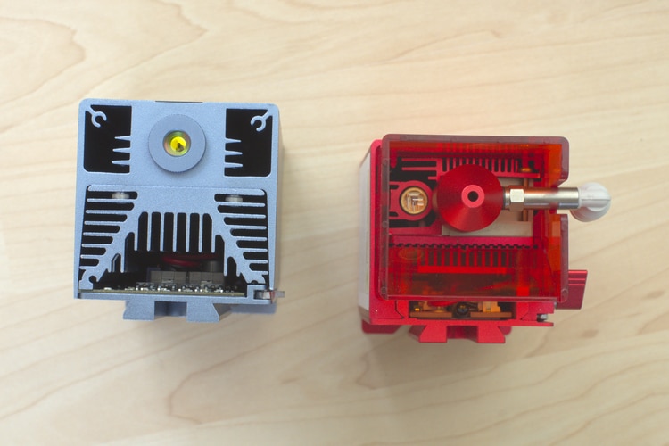
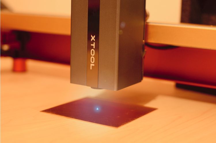
On the 20W module, there is a separate laser diode that projects red crosshairs down on the material to help with alignment. On the infrared module, there is no second diode visible. But after installing and powering the module, I saw that there is a red dot that indicates the position of the laser. This red dot comes through the same lens as the infrared laser.
Installation
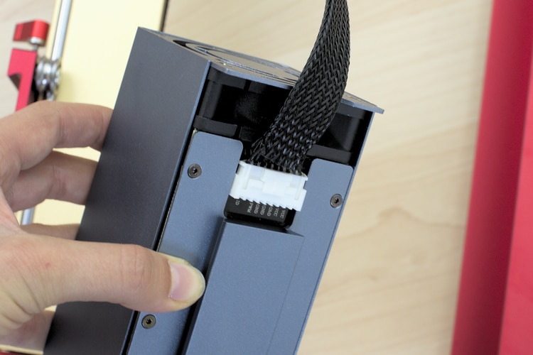
Installation is pretty simple. First, you need to unplug the 20W module and put it aside. Then connect the cable to the infrared module and slide it into the module holder. You also have to change the power supply to the 150W version. (You only need to do this once as you can also power the 20W laser with it and don’t need to change back again.)
Software
Before any use of the infrared laser module, it is important to make sure the firmware of the D1 Pro and xTool Creative Space (XCS) are updated to the latest version. Here is how you do that:
Check/Update xTool Creative Space
- Start XCS
- Click on the “Settings” button in the top left.
- In the pop-up that opens, click on the “Check for updates” button.
- If you already have the latest version, everything is fine. Else run the update.
Check/Update the D1 Pro Firmware
- Power on the D1 Pro and connect it to your computer with the USB cable.
- Start XCS
- Click on the “Connect device” button in the upper right.
- In the pop-up that opens, select your machine.
- Click on the gear icon and then click on “Check for updates“.
- If a new firmware version is available, set the little upload switch on the PCB board below the power button to “ON“.
- Run the update.
- After the update has finished, set the upload switch back to “OFF“
Safety Note
Infrared light is not visible to the human eye. You won’t be able to see the beam but it can still cause damage to your eyes. Always wear proper safety glasses when operating the laser.

In addition, please be aware that cutting or engraving always produces smoke and/or fumes. Breathing in those fumes is not healthy. So only use the laser outside or in a very well-ventilated area or get an enclosure with an exhaust system to vent outside.
Never leave the laser running unattended and have a fire extinguisher nearby when processing flammable material.
Setting the Focus
It is important to set the focus of the infrared laser module very accurately. This is because its focal length is only 20 mm and not 40 mm as with the blue lasers. The shorter focal length means that the depth of focus (DOF) is considerably smaller too.
The depth of focus describes the distance range in which material has to be, to get good cutting/engravings. The depth of field of the blue laser modules is about 4 to 6 mm. The depth of field of the xTool infrared module is only 1 mm.
In practice, this means if you for example set the 20W laser 1 mm too far away from your material. You probably won’t notice this in the result as there is only a very small loss in cutting power and engraving detail. However, with the infrared module, this error can result in the laser not engraving the material at all.
Checking the Module Holder
I had already noticed that my module holder was slightly loose when using the 20W laser but as it still performed well, I did not give it a second thought. But as there was a high chance this might cause issues with the infrared laser, it was clear to me, I needed to fix this. xTool has published a guide on how to adjust the holder of the laser module to make sure it is not loose. Altogether the fix took less than 10 minutes and now there is no more wiggle.
Performing a Ramp Test
A good way to find the best focus distance is to perform a ramp test. Here is how I would recommend performing it for the infrared module:
- Take a piece of material that should be at least 10 cm (4 in) long and place it parallel to the X-Axis (left to right). Then elevate one side by placing something under it about 1 cm tall.
- Move the laser module approximately to the middle of the material. Lower the focus bar and then adjust the height of the module till the focus bar touches the material.
- Move the laser module to the left end of the material.
- In XCS or Lightburn draw a straight line the same length as your material.
- Run the job. The laser will burn a straight line from left to right.
- Don’t move the material and look where the line is the deepest/thinnest.
- Place your module over that point and measure from the material to the bottom of your laser module. This is your optimal focal distance.
With my infrared module, I found that the focal length setting bar was pretty much spot on when I lowered it carefully so that it just touched the material.
Test Engravings
Inside the 1064 nm xTool infrared laser module is a pump laser with photo-electric conversion. It uses a natural crystal that is stimulated to generate the laser. Since no two natural crystals are exactly the same, the same settings won’t produce the same results for every user.
I will still show you the settings I used for my test but bear in mind that you will have to do your own test to get the best results.
All tests were done directly on the material without any marking spray.
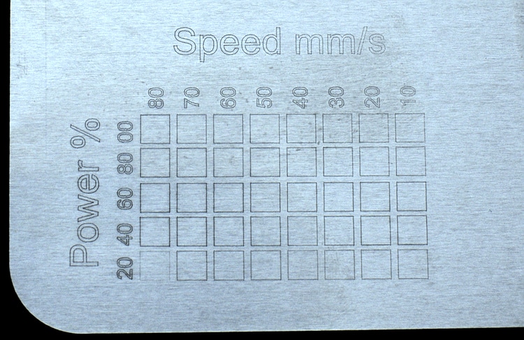
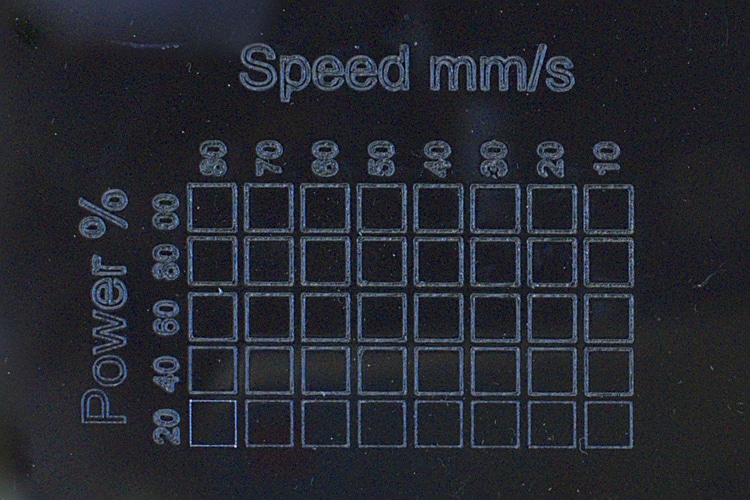
Aluminum
The first material I tested was uncoated aluminum. I scored a test grind with power settings from 20 to 100 % and speed settings from 80 to 10 mm/s. Even with the lowest power and highest speed, there was already a visible mark and at 40 % power and 80 mm/s, I got a clearly visible square. Running the laser at higher power/less speed does not really change the appearance of the score.
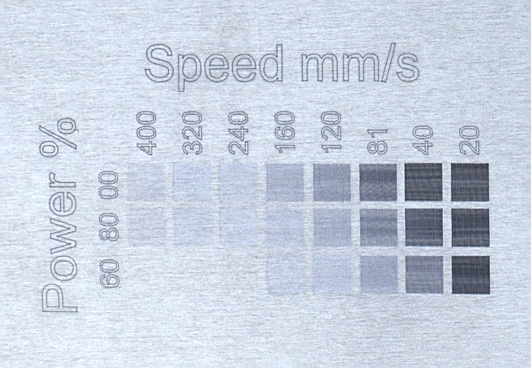
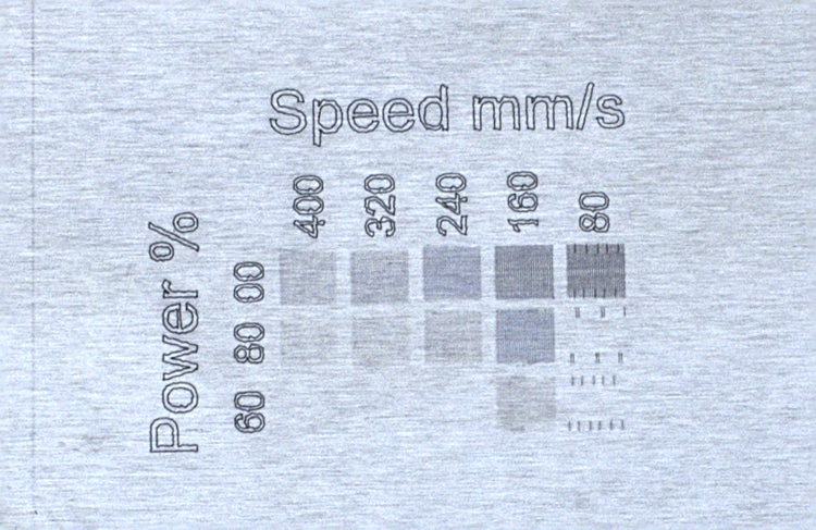
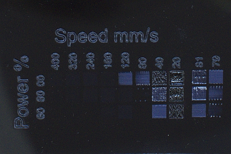
Next, I did an engraving test. I tested with power settings from 60 to 100 % and speed settings from 400 to 20 mm/s. With these settings, you can get everything from a very light engraving to a nice dark gray.
One thing I have to note here, is that I had a problem when I tried engraving at a speed of exactly 80 mm/s. As you can see in the image below I got some strange lines and not a consistent engraved area.
I had the same result on different materials and also remade the XCS file twice from scratch. I assume this is a software issue. When I used a speed of 81 mm/s the error disappeared and also lower speeds (e.g. 40 or 20 mm/s) worked fine.
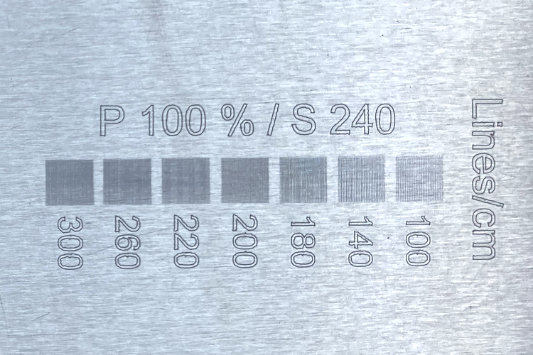
Afterward, I also did a test for the lines/cm setting. This setting is relevant for engravings only and specifies how many lines per cm are used to fill the area to be engraved. I found that up to 140 lines/cm the individual lines are clearly visible. At 180 lines/cm they start to merge together and from 200 on you can’t distinguish individually engraved lines with the bare eye anymore.
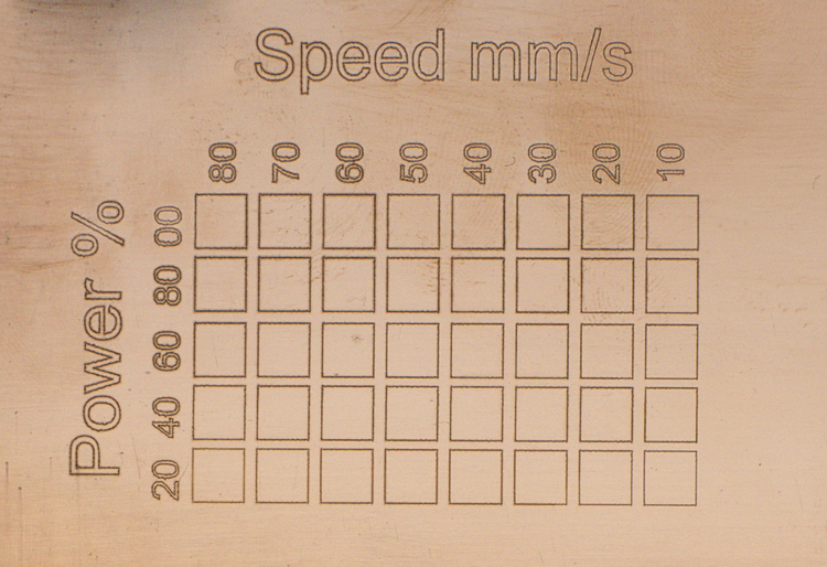
Black acrylic
The infrared module works great for scoring black acrylic. Even at only 20 % power and a speed of 80 mm/s, there is a clearly visible mark.
When engraving black acrylic I found that there is a relatively small range to get good results. At too-high speeds/low power there is no mark at all and when using less speed/higher power the result quickly looks melted. So I like the xTool infrared laser for scoring but not for engraving areas on acrylic.
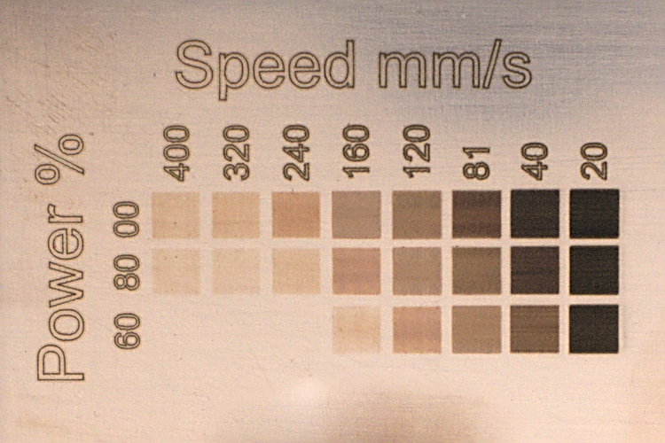
Copper
The third material I tested was solid copper. Here the results were similar to the previously used aluminum. I got a nice score running at 20 % power and 80 mm/s speed. The engraving test also looks very good. By modifying speed and power you can get results from very light to pretty dark.
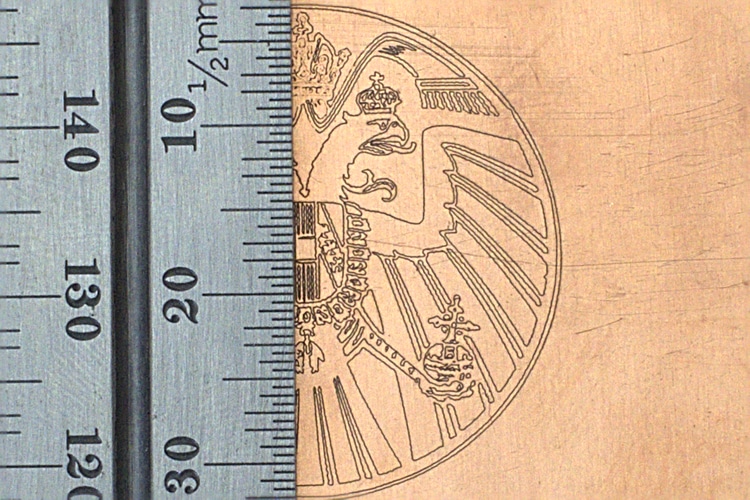
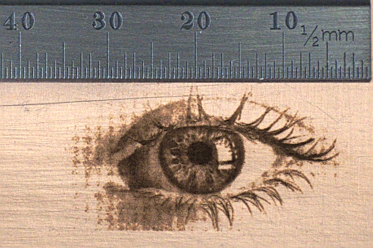
Below are two engraved images the first one is just scored lines. Even the very fine details came out nicely. The second one is a grayscale engraved from the image of an eye. I honestly did not expect that it would be possible to get such a detailed engraving of a photo on metal.
Final Thoughts on the xTool Infrared Module
Compared to the 20W module requires a bit more attention to detail and testing to find the right settings. But once you have your settings dealt in the results on metal are definitely worth it. The small spot size of the laser beam makes very detailed engravings possible and sofar
I will keep using the xTool D1 Pro and continue to write more posts about my long-term experiences and learnings.
If you don’t want to miss it subscribe to the newsletter!
I have the D 1 10-watt pro and the 1064 infrared also
Thank you much for the review, you helped me to get my laser set up correctly!