
Some weeks ago, I wrote a post about a simple way to make laser cut right angle gears. The results looked promising but I was not able to make any detailed tests because my method of mounting the gears on wooden dowels as axels did not work as expected.
My original plan was to fix the gears on the wooden dowels by using press fitted spacers. The problem with this was that the tolerances of the wooden dowels were not tight enough for this to work. At some places, the spacers were too loose and would start to move after a few turns or the spacers would sit so tightly that I could barely move them.
So I decided to change my plan. I wanted a system that made it possible to:
- adjust the position of the gears on the axle
- non-destructively disassemble the parts
- and was cheap/easy to make
I finally
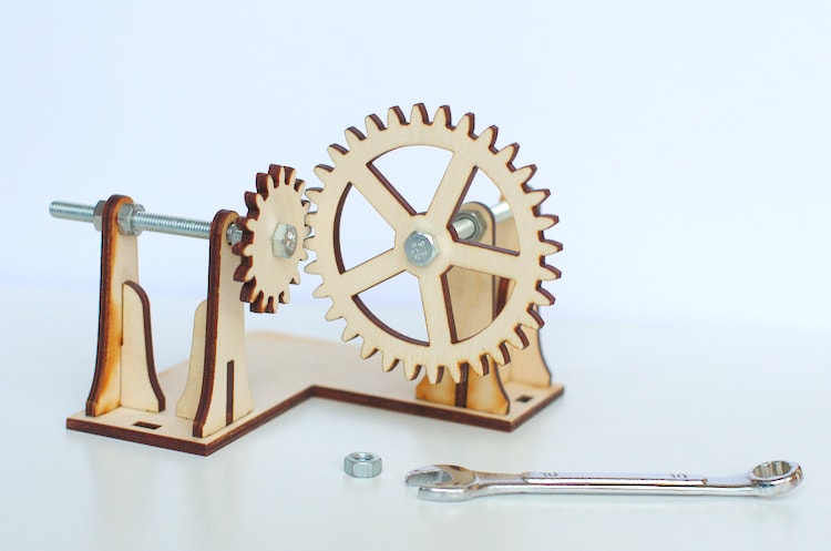
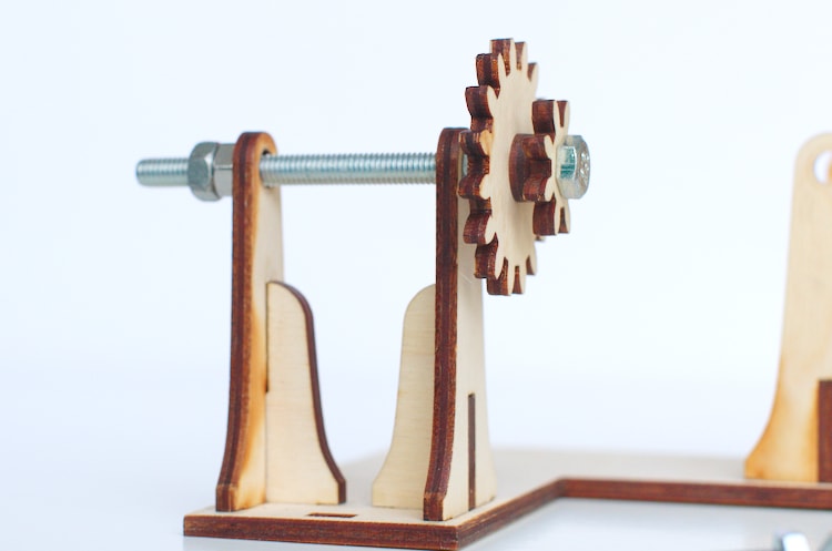
Here you can see the gears mounted on the bolts. I used two nuts to position the gear. The two nuts are tightened up against each other. Between the nuts and the gear, there is just enough room for the gear to turn freely.
I was a bit concerned about friction but the gears turn quite easily. For my testing purposes, this is definitely good enough.
Two addition nuts are used to hold the bolt in the correct position inside the test frame. It is really easy to fine-tune the way the gears are meshing by simply loosening one nut and then turning the bolt slightly in one or the other direction.
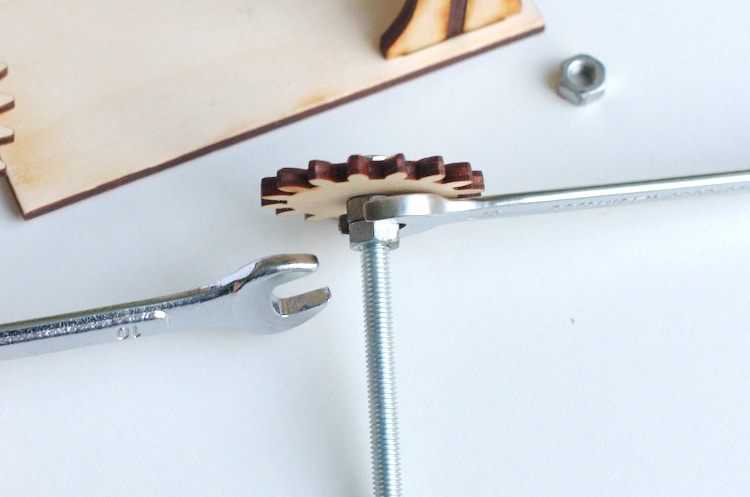
All in all, I am pretty happy with this set-up. The assembly could be a bit easier because you need two wrenches. One to hold the first nut in position and a second one to tighten the other nut. But it is working really well.
Right Angle Gears – Test Results with Nuts and Bolts
So finially I want to share with you the results of my tests regarding the right angle gears.
I made a short video to show you how the right angle gears mesh. When adjusted correctly there is only

The video above shows the regular spur gears. The video below displays the gears with the profile inset by 0.5 mm. Both setups were working fine. The inset gears had more backlash but they were also running a bit smoother and were less likely to jam when not aligned 100 % correct.
Shafts with multiple Gears
One thing I really like about this combination of nuts, bolts
Hey! Is it possible we could get the laser cutting files for this? A friend and I are trying to do a project that includes this type of movement. Thanks!
I’d also appreciate some downloadable svg’s for these gears – I’m teaching a maker class for middle schoolers and it’d save me a ton of time. Thanks for considering!
Hi. Have a look at bearings. They will allow you to thread the bolt through without having to mess around with 2 nuts and still have free turning cogs. And if you start to mess around with entrapment cogs and clockwork you will need them 🙂 looks amazing tho!!
Yes, bearings would definitely be an option, but I was just trying to work with what I already had at hand.